

OpenPLC is an initiative by FOSSEE, to engage the polytechnic, engineering and other technical students, in hands-on PLC programming experience. We envision to bridge the gap between theory centric academic training and skill based industry requirements. We use Free/Libre and Open Source Softwares - LDMicro, 4diac and PLCOpenEditor - along with affordable open-source hardware designed at IIT Bombay.
Students across engineering, polytechnic and industrial training institutes, adding up to about a million, need to be educated in PLC every year. If we include re-skilling the workforce, the number becomes even larger. In fact, the Indian Government has projected skills training for half a billion people. Most of these students lack hands-on skills as the machinery is expensive , making it mostly unaffordable for the academic institutions. Even if they are available, students are forbidden from using it out of fear that they might get into disrepair. Existing PLC’s are also restricted to predefined set of experiments and thus lack versatility. They are also closed and interiors are made inaccessible, making it a black-box.
Affordable PLCs are the need of the hour in countries like India. It is important, however, that they follow established standards, so that whatever one learns through these PLCs will be applicable in the industrial setting, without major changes.
What is a PLC?
A Programmable Logic Controller (PLC) or programmable controller is an industrial digital computer used for automation of various electro-mechanical processes in industries. These controllers are ruggedized to survive in harsh situations. The program is written on a computer and is downloaded to the PLC. These loaded programs are stored in non – volatile memory of the PLC.
The Programmable logic controller functions in four steps:
-
Input scan: The state of the input is scanned which is connected externally. The inputs include switches, pushbuttons, and proximity sensors, limit switches, pressure switches.
-
Program scan: The loaded program is executed to carry out the function appropriately.
-
Output scan: The input sources have a control over the output ports to energize or de-energize them. The outputs include solenoids, valves, motors, actuator, and pumps.
-
Housekeeping: The hardware communicates with the programming terminals, performs internal diagnostics etc.
Programming PLC’s:
While Ladder Logic is the most commonly used programming language, it is not the only one. Most common programming languages for PLC’s are:
-
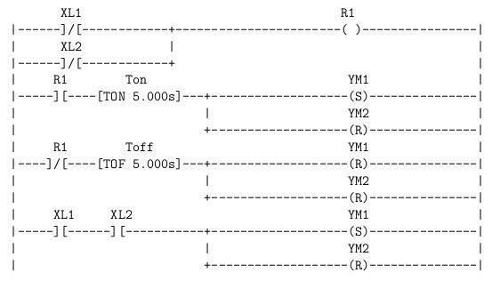
Ladder Diagram: Graphical programming language, programmed with use of simple contacts, coils, timers, counters, shift-registers etc. For example
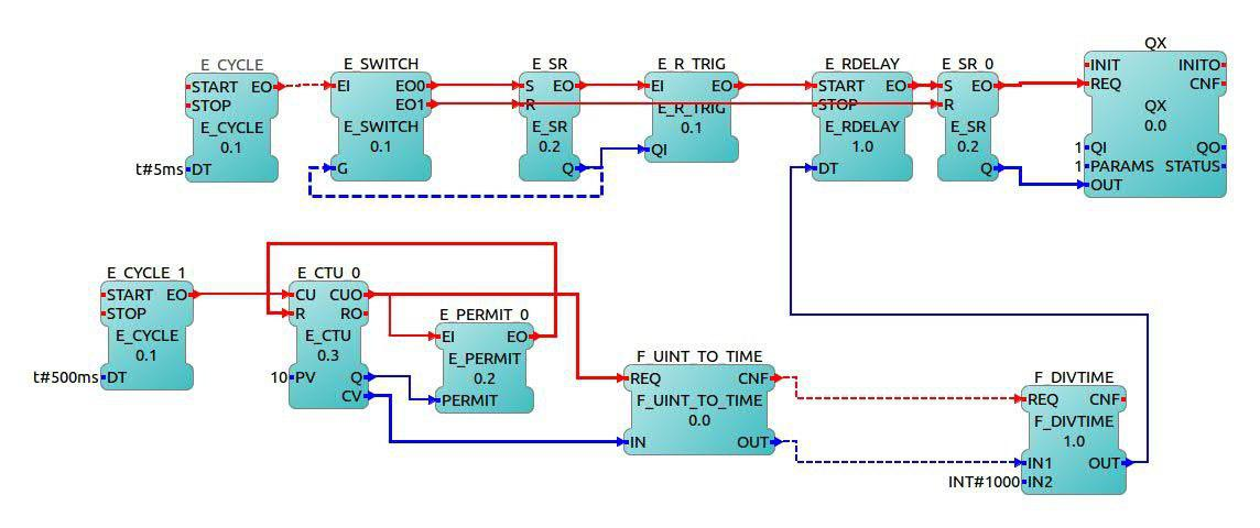
- Function Block Diagram: A graphical language for depicting signal and data flows through reusable function blocks. For example:
- Structured Text: A high level text language that encourages structured programming. For example:
|
- Instruction List: A low level “assembler like” language that is based on similar instructions list languages found in a wide range of today’s PLCs. For example:
|
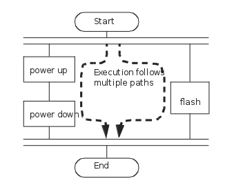
-
Sequential Function Chart: An overview of the control system in which the basic building blocks are entire program files, where each program file is created using one of the other types of programming languages. For Example: